
|
|

|
|
|
|
|
 11-10-2019, 11:22 PM
|
#1 | |||
|
FF.Com.Au Hardcore
Join Date: Jun 2010
Location: Perth
Posts: 1,315
|
Quote:
Just curious how you plan to get the Sync2 working? Is the Arduino chip able to replace messages? (Re-play certain FGX messages when another FG2 message is detected? I believe my CAN Analyser can do that, but haven't played with it yet. There is a CAN conversion specialist in Australia that makes it possible to plug-and-play swap LSX engines into Subaru BRZ. Maybe he would be interested in developing a converter for fitting the Sync2 and Sync3 into Falcons? https://www.agtengineering.com.au/ca...tive-solutions Some very impressive things going on there. By the way, If you read the reviews of Sync2, the reviews are that it is a rather poor system (comes with Windows bugs), and much better to try to retrofit Sync3. Cheers, |
|||

|

|
| This user likes this post: |
|
12-10-2019, 12:07 AM
|
#2 | |||
|
Away on leave
Join Date: Apr 2019
Location: ACT
Posts: 1,732
 
|
Quote:
Gonads of steel may be required. (Oh, 4 replies in a row - must be time for bed. No PMs BTW.) |
|||
|
|
|
|
12-10-2019, 12:27 AM
|
#3 | ||
|
Regular Member

Join Date: Oct 2019
Location: Adelaide, SA
Posts: 43
|
Hi JasonACT,
I did some more testing on my old board again, but not happy with my results... Ill stop testing for now until i replace this MOSFET, and find my other multi-meter. which is better quality. If you would like me to send my old one, PM me and we can arrange something. but ill probably keep it for a few weeks, just in case something happens with the second hand one i just bought. |
||
|
|
|
| This user likes this post: |
|
12-10-2019, 11:16 AM
|
#4 | |||
|
Away on leave
Join Date: Apr 2019
Location: ACT
Posts: 1,732
|
Quote:
It would be fairly easy to replace that whole 9v / ?v (dimmed) LED Driver part with a custom mod (9v regulator, Arduino & MOSFET - PWM driven with a new plug for the red/black wires). So one way or another, I reckon it will live again. I'm going to try to link pins 1 & 5 on the large board today - to see if it'll power up without the small board plugged in.. With them sandwiched, it's hard to take any readings while it's on. Last edited by JasonACT; 12-10-2019 at 11:37 AM. |
|||
|
|
|
| This user likes this post: |
|
08-10-2019, 12:09 AM
|
#5 | ||
|
Away on leave
Join Date: Apr 2019
Location: ACT
Posts: 1,732
|
(The lines on the LCD may just be because there's no common ground, with the foreign 9v supply. Throws me though, using the ~12v positive as a ground, some engineer somewhere is proud of themselves, I'm sure.)
|
||
|
|
|
|
08-10-2019, 12:19 AM
|
#6 | ||
|
Away on leave
Join Date: Apr 2019
Location: ACT
Posts: 1,732
|
Yeah, that's what the OP did. He's happy now, so I'm happy for him too. I've kind of stolen his thread though
 The voltage input to the LE80 is the +12v input of the car - so I'm surprised that isn't getting through any more. There's a choke on the larger board, maybe that's gone? Hard to believe though? What were the circumstances of your screen dying? (Sorry, I'm going to have to bail - got work tomorrow.) |
||
|
|
|
|
08-10-2019, 12:35 AM
|
#7 | ||
|
Regular Member
Join Date: Oct 2019
Location: Adelaide, SA
Posts: 43
|
Well, I really dont know why my screen just died.
I sent to work last Wednesday and it was working fine, I jump in my car to go home at the end of the day and nothing, just blank screen. It was a hot day though here in SA, so it could of been that maybe. I called Zooper! as I have a premium protection warranty plan with them because I only bought this car in February and they wont cover it. They had advised me that ford should be exchanging them free of charge, being an apparent common fault. I called 2 ford dealers and asked to speak to there service department to which I was advised they were busy and would call me back, they never did. So I took the bob the builder approach hahaha |
||
|
|
|
|
08-10-2019, 12:25 AM
|
#8 | ||
|
Away on leave
Join Date: Apr 2019
Location: ACT
Posts: 1,732
|
The board still may need the +20v to produce the correct screen output (explains why the engineer did all this). So it's still a good possibility there's a simple fix (not a $700 one).
|
||
|
|
|
|
08-10-2019, 06:16 PM
|
#9 | ||
|
Away on leave
Join Date: Apr 2019
Location: ACT
Posts: 1,732
|
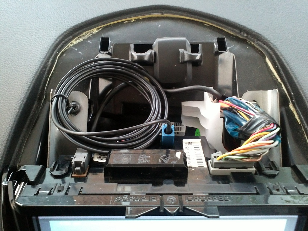
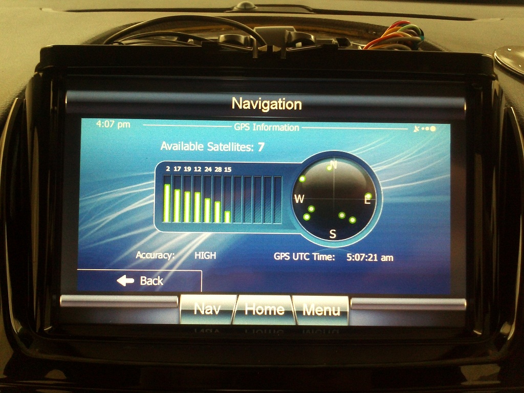
I had another win this afternoon.. The SAT NAV aerial arrived in the mail. This was the last component I needed to put back the last cover which has been off since last Friday:
|
||
|
|
|
| This user likes this post: |
|
08-10-2019, 07:08 PM
|
#10 | ||
|
Away on leave
Join Date: Apr 2019
Location: ACT
Posts: 1,732
|
1/ Pretty sure they are compatible, mine reconfigured itself as a Territory model by accident.
2/ No, I didn't have to "code" it to my car (the radio-part requires that though) it "just works". |
||
|
|
|
|
08-10-2019, 07:13 PM
|
#11 | ||
|
Away on leave
Join Date: Apr 2019
Location: ACT
Posts: 1,732
|
Try and get one with the same number of climate control zones as you have!
|
||
|
|
|
|
08-10-2019, 07:38 PM
|
#12 | |||
|
Regular Member
Join Date: Oct 2019
Location: Adelaide, SA
Posts: 43
|
Quote:
I have a single zone, will it not work if it doesnt match? |
|||
|
|
|
|
08-10-2019, 07:44 PM
|
#13 | ||
|
Away on leave
Join Date: Apr 2019
Location: ACT
Posts: 1,732
|
The fan buttons are on the left in single zone models, they are in the middle for dual zone models. The LCD unit is coded to read the buttons in the particular position for the zone programming, but the button circuit boards are identical.
So, you would have to modify your buttons to include the "middle" fan rocker button if you got the wrong one (which is what I did). So I've got a passenger temp button that does nothing! (Until I re-program my HIM to dual mode and buy the extra components to add in the 2nd AC/Heater mixer unit.. still might do that, except I rarely have a passenger - so it's low priority.) |
||
|
|
|
|
08-10-2019, 09:25 PM
|
#14 | ||
|
Away on leave
Join Date: Apr 2019
Location: ACT
Posts: 1,732
|
I don't paste images, I upload them to my photo gallery and edit the thumbnail link to remove the "thumbs/" bit so the full image shows.
You can see the large circuit board trace going from the part you say has power, to the one you say doesn't have power:  Is it burned out? |
||
|
|
|
|
08-10-2019, 09:46 PM
|
#15 | |||
|
Regular Member
Join Date: Oct 2019
Location: Adelaide, SA
Posts: 43
|
Quote:
The trace doesn't look burnt out. 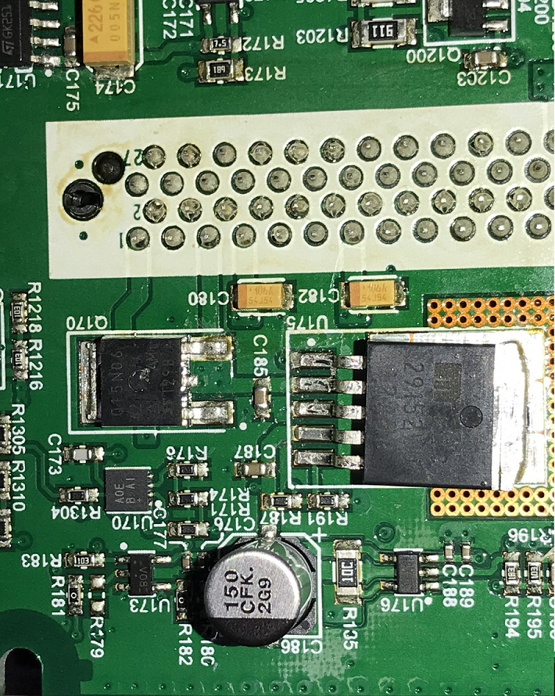
|
|||
|
|
|
|
08-10-2019, 09:55 PM
|
#16 | ||
|
Away on leave
Join Date: Apr 2019
Location: ACT
Posts: 1,732
|
Does your multimeter have a buzzer to tell you when the resistance is low enough to consider it basically a wire? I think it needs to be properly tested / re-connected - and the connection also wired to the LE80's pin 8.
I think I'm out of ideas otherwise. Other than to say, I think it's this board... So even if you get a dual zone replacement, you can use your LCD with the replacements smaller board (the one in the picture) and be safe that you will have the correct # of zones. |
||
|
|
|
|
08-10-2019, 11:36 PM
|
#17 | ||
|
Away on leave
Join Date: Apr 2019
Location: ACT
Posts: 1,732
|
I think I see the problem:

|
||
|
|
|
|
08-10-2019, 11:49 PM
|
#18 | ||
|
Away on leave
Join Date: Apr 2019
Location: ACT
Posts: 1,732
|
For the record, I've reported XRPete as being a bogus user. R173 are different resistors in his posts.
|
||
|
|
|
|
09-10-2019, 12:34 AM
|
#19 | ||
|
Away on leave
Join Date: Apr 2019
Location: ACT
Posts: 1,732
|
Please disregard all information in this thread for the last 24 hours. It's unreliable, and I want to do the right thing by the public, even if others (no names) don't care.
|
||
|
|
|
|
09-10-2019, 12:47 AM
|
#20 | ||
|
Regular Member
Join Date: Oct 2019
Location: Adelaide, SA
Posts: 43
|
Im sorry but i am not a bogus user, nor have a been bogus in anyway.
im not sure why you are saying that? below is a full picture of my board, please advise what you are seeing thats different.  www.fordforums.com.au/photos/showfull.php?photo=74802 |
||
|
|
|
|
09-10-2019, 12:53 AM
|
#21 | ||
|
Away on leave
Join Date: Apr 2019
Location: ACT
Posts: 1,732
|
Count the holes in the heat sink that the 5 pin large chip covers. One has 4, one has 5 and this latest one has 6.
See you later, buddy. (Not to mention the angle of the large 5 pin chip in each. Or the faded part number in one photo. Or the solder base vs the reglator offset / mask in all 3! Go away.) |
||
|
|
|
|
09-10-2019, 01:09 AM
|
#22 | ||
|
Regular Member
Join Date: Oct 2019
Location: Adelaide, SA
Posts: 43
|
Im not here to waste anyone time, and i am very grateful for the help you have provided me. but i am not bogus, i have be honest and truthful in ever post.
you are comparing 1 photo that was cropped and un-cropped, and at different angles. i literately just took these last photos and uploaded them to show you a shot for shot comparison with flash on and without. see below. my apologies if you feel that i have wasted your time or if ive miss lead you in any way.. with flash  without flash 
|
||
|
|
|
|
09-10-2019, 01:26 AM
|
#23 | ||
|
Away on leave
Join Date: Apr 2019
Location: ACT
Posts: 1,732
|
I'll let the moderators decide (or the public) as they are very similar boards, I agree, yet different enough in spectacular ways. So I'm not going to entertain further effort on this unless a long standing member says they can see how I've got it wrong (which is quite possible, I'm known for it).
|
||
|
|
|
|
09-10-2019, 01:31 AM
|
#24 | ||
|
Regular Member
Join Date: Oct 2019
Location: Adelaide, SA
Posts: 43
|
Ok, thank you Jason...
and if i do end up buying a the screen from the wreckers, which probably will end up doing. I am more than happy to send you this one, if you want have a tinker with it. once again, apologies to you and everyone, if i have cause any problems here.. |
||
|
|
|
| This user likes this post: |
|
09-10-2019, 01:38 AM
|
#25 | ||
|
Looking for clues...
  
Join Date: Jan 2005
Location: Morayfield
Posts: 22,888
|
Stand down, JasonACT. XRPete appears to be posting in good faith from what I see, with no bogus intentions.
Continue with the research.
__________________
Swannys Fundraiser for the 2024 MS Brissie to the Bay Bike Ride 2016 Ford Falcon FG/X XR6 Turbo you beaut ute 1985 XR4Ti Sierra - Build Thread 1971 Fairlane 500 and... a collection of Jeep Towpigs and... two collections of rust and some new plastic bits roughly shaped like an F-Truck and.... some spare metal bits with holes in them |
||
|
|
|
|
09-10-2019, 01:46 AM
|
#26 | ||
|
Away on leave
Join Date: Apr 2019
Location: ACT
Posts: 1,732
|
Ok, thanks Swanny. I apologise, I hope XRPete, you find your solution and cheaply! I'll answer any other questions you have, if I can.
|
||
|
|
|
| This user likes this post: |
|
09-10-2019, 02:16 AM
|
#27 | ||
|
Regular Member
Join Date: Oct 2019
Location: Adelaide, SA
Posts: 43
|
Thank you Swanny and JasonACT, and my apologies once again.
JasonACT, thank you very for your help so far, I really do appreciate it. Ill advise over the next couple of days what action Ill take with this screen, whether I purchase a second hand one from this wrecker (SA Auto Spares). |
||
|
|
|
| This user likes this post: |
|
09-10-2019, 02:41 AM
|
#28 | ||
|
Away on leave
Join Date: Apr 2019
Location: ACT
Posts: 1,732
|
To be honest (and I'm going to bed as soon I post this) I've got to hand it to you, for taking photos that show the same thing, but in such a different way each time. You are an artist, even if you didn't mean it. Don't apologise.
|
||
|
|
|
|
09-10-2019, 10:23 AM
|
#29 | ||
|
Away on leave
Join Date: Apr 2019
Location: ACT
Posts: 1,732
|
The guys at work here are having a laugh, half of them say "different" the other half say it's just the angle. So, I apologise again!
|
||
|
|
|
| This user likes this post: |
|
09-10-2019, 06:24 PM
|
#30 | ||
|
Away on leave
Join Date: Apr 2019
Location: ACT
Posts: 1,732
|
U170 (says "AOE B A1" mine says "AOE I AH" - I can't find any data on these) has R1304 which also has the same 12v input on the trace going between the two. C173 has 21v on the trace going between those two. I suspect this device generates the higher voltage, but that's a total guess.
That would be a difficult part to desolder and replace, even if you could order them. It might be a case of creating a new circuit to replace it, which is getting vastly more difficult. I'll have to see what devices there are like what I think it is. |
||
|
|
|
| This user likes this post: |


 Hybrid Mode